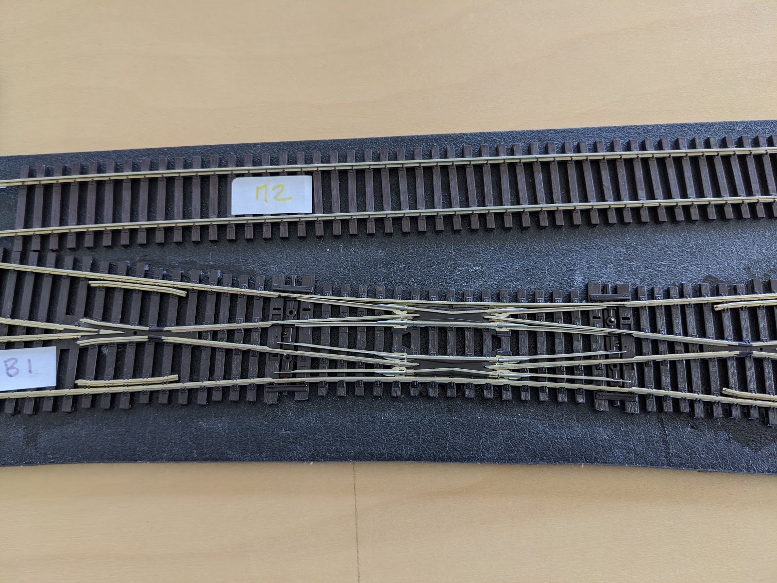
I forgot to mention one rather important detail in my previous post: how to configure the ESU ECoS for a Peco double slip switch. On the ECoS, a double slip switch has only one digital address. The thing to know is that the ECoS will automatically assign the next address to the second motor.
Therefore, the double slip switch B1 has addresses #1 (TB1a) and #2 (TB1b).
Tuesday, May 26, 2020
Monday, May 18, 2020
ESU ECoS - Engine image
This is a short post to list the steps to add an engine image on the ESU ECoS:
1- Login to http://www.esu.eu/en/downloads/loco-pictures/
2- Download the image on your computer
3- Login to the ESU ECoS http://192.168.1.197/en/index.html
4- Upload the image
5- Restart the ESU ECoS


1- Login to http://www.esu.eu/en/downloads/loco-pictures/
2- Download the image on your computer
3- Login to the ESU ECoS http://192.168.1.197/en/index.html
4- Upload the image
5- Restart the ESU ECoS
Saturday, May 16, 2020
Wiring - part 3
Terminal blocks
After the last two parts of the wiring, I was not very satisfied with my terminal blocks and decided to try out another type of terminal blocks. Here are the links:
- Terminal blocks of various sizes: https://www.amazon.com/gp/product/B08135QF67
- Crimping tool: https://www.amazon.com/gp/product/B07Q4MG4BW


The main advantages of this terminal compared to the one I've been using so far is the ability to connect wires from very different gauges and the simplicity of connecting in parallel.
We can compare those two versions:


Tortoise switch motors
Once I wired the 3 sections on each side of the switches, I took on the installation of the Tortoise switch motor. I glued some leftover trackbed between the plywood and the motor to prevent vibrations.


I then mounted the motor with the provided spring (I advise against using anything else: I have one switch with some other wire and I think it is not flexible enough and might damage the switch over time).


I then started the easy wiring of the motors, that's to say without any power to the frog (green wire).


Time for a quick test:
Peco switches
At this stage, I decided to glue these two switches in place on the trackbed with the Woodland Scenics glue:


Temporary wiring
I was ready to see some machines running and omitted to wire the section detection; so based on the diagram I connected all the red wires together:


What we were waiting for!
And finally:
Sunday, May 10, 2020
Wiring - part 2
I continued with the diodes board for the switch decoder. I haven't found yet the appropriate connectors to solder on the PCB, so I'm soldering small wires; all of those components are very cheap, so I can always improve this component later on.


There are two things to configure on the Lenz LS150:

PCB & Diodes


From there, I just have to connect the PCB to the switch decoder following the documentation:

And it looks like this:

Configuring the switch decoder
There are two things to configure on the Lenz LS150:
- Digital address of each switch command
- Pulse duration of the output
The documentation is quite clear and easy to follow.

The idea is that, once the switch decoder is in "programmation" mode, I need to use the address field on the configuration in the ECoS to send values on the LS150. For the tortoise switch motor, a pulse duration of 3.5sec seems appropriate - 3sec might be okay too.
All together ...
And here's the result:
Sunday, May 3, 2020
Wiring - part 1 of many ...
After cleaning up the shop last weekend, I was finally able to work on the layout. My priority is to have trains moving as soon as possible. To that end, I thought I would wire a small section of the layout as explained in this previous post: Partially putting everything together

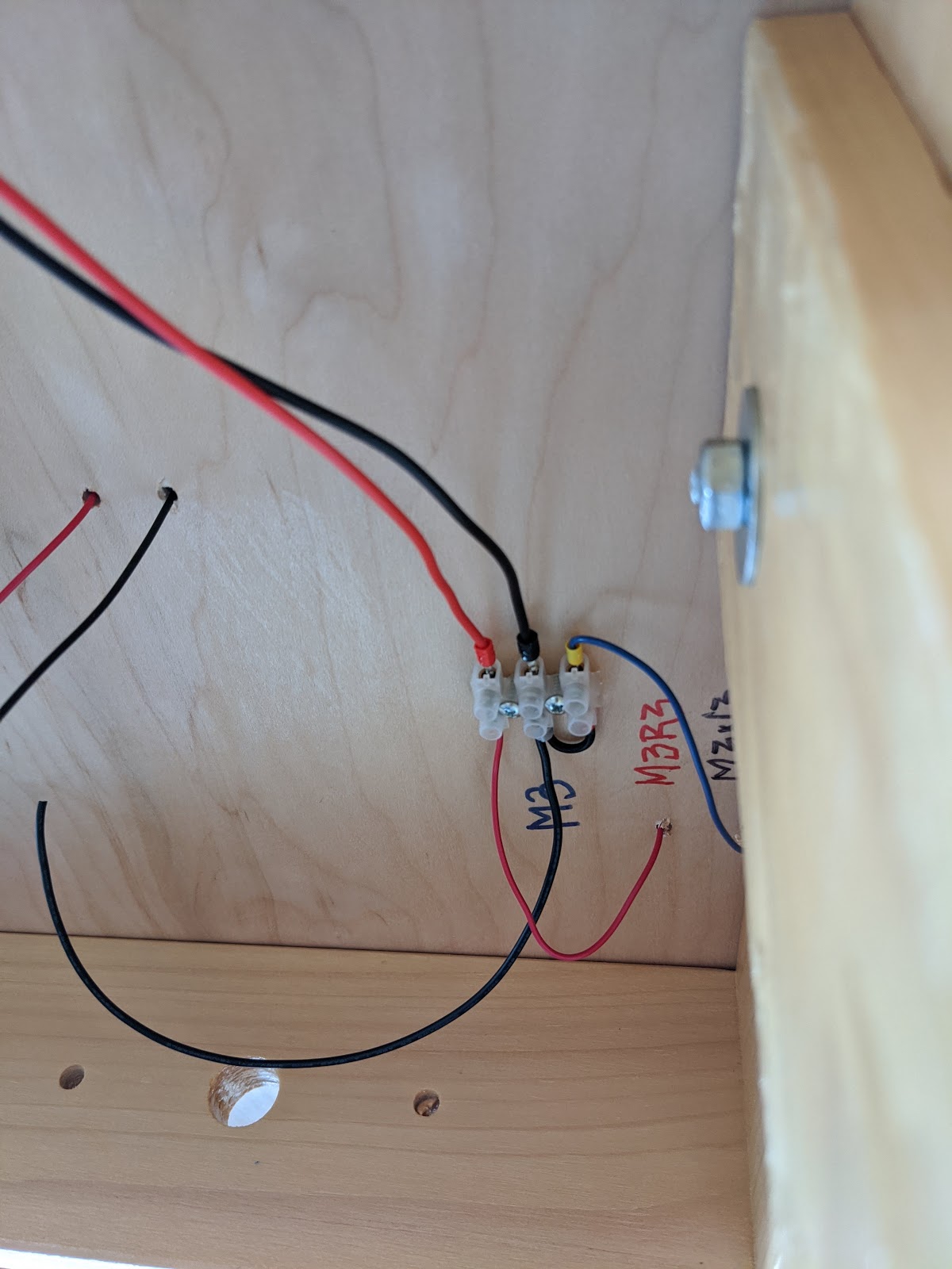
I'm starting with the M3 section. All black wires should be connected together, whereas the red wires need to be separated for block detection. I'm using AWG 18 so far for this M3 section, but based on this website, I should be using AWG 12 or 14 for the bus. I will adjust as needed.
Here's how it looks so far.
1. From the far end of section


Since all the black wires should be connected to each other, I've left a black wire on each terminal to connect to the neighboring sections. Then, I ran out of wires ...
Following the same previous post, I've started to solder diodes on a PCB for the switch decoder:


I'm starting with the M3 section. All black wires should be connected together, whereas the red wires need to be separated for block detection. I'm using AWG 18 so far for this M3 section, but based on this website, I should be using AWG 12 or 14 for the bus. I will adjust as needed.
Section M3 wiring
Here's how it looks so far.
1. From the far end of section
2. Middle of section

3. Near end of section

Since all the black wires should be connected to each other, I've left a black wire on each terminal to connect to the neighboring sections. Then, I ran out of wires ...
PCB & Diodes
Following the same previous post, I've started to solder diodes on a PCB for the switch decoder:

Saturday, May 2, 2020

Subscribe to:
Posts (Atom)