I'm almost done with ballasting the area in the back, so I need to think about where I'd need to put the scenery divider. To do that, I need to know how things are positioned on the front part.
First, I cleaned up the layout, then I placed the map where it should fit:
At that point, with a small screwdriver and a hammer, I marked every line intersection to go through the paper. Then I traced the outlines directly on the layout.
I'm quite happy with the outcome because I can fit the all area without squeezing anything; except the fret hall and the road crossing on each end - which I knew.
Today, I didn't have time to continue on building draft structures, so I focused on pictures of the facades.
See below:
11 rdM #111 - 11 rue des Martyrs - Parcelle 111
13 rdM #110 - 13 rue des Martyrs - Parcelle 110
15 rdM #109a - 15 rue des Martyrs - Parcelle 109
15 rdM #109b - 15 rue des Martyrs - Parcelle 109
For this last one, I had to combine two pictures together since the house is quite tall. I fixed the perspective and dimensions on each of them before combining them and the fit is very good.
Now that I have the outline at the exact scale, I can easily create draft building out of foam boards. There's nothing special about this task; just cutting and gluing foam boards at the right dimensions. I wrote the house number in the back and glued a picture of the facade in the front (as explained at the end of this post).
After my previous post, I was still thinking about how to print the DXF file at the exact scale, so I can see how it would look on the layout. I unsuccessfully tried various software and ultimately started to look deeper into AutoCAD. Thankfully, there's a 30-day free trial of AutoCAD LT that seems to be a lighter and cheaper version of AutoCAD.
Those two videos were the most helpful:
After multiple attempts, here are the steps I took in AutoCAD.
Rescaling
As mentioned in my previous post, CAD software do not have units, but rather "drawing" units. The "real" units will come into play when exporting into PDF. Therefore, I decided that one drawing unit will be 1mm at HO scale. Going back to my reference point from my previous post, 25rdM #100 should have a width of 103mm (25 rue des Martyrs that is lot #100 on the cadastral plan).
Here are the steps in AutoCAD:
When opening the DXF file, most CAD software will not display much at all. The first step is to click on "Zoom Extents". This will zoom out or in to fit all of the objects in the drawing to the edges of the screen so you can see the entire drawing.
Select all components on the drawing
Scale using the reference point
Measure again to make sure
Layout and printing
In AutoCAD, there are usually two tabs at the bottom: a model and a layout. The model is the actual drawing and the layout is used for formatting before printing. Therefore, you can have multiple layout tabs (I don't know about models).
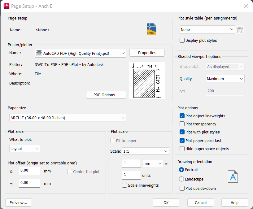
When starting a new layout, AutoCAD asks for a page setup. This is what I have in my case:
The main items to note:
Printer is an export to PDF
Paper size is Arch E, which is the largest Staples can print
==> Scale is 1:1 and 1mm is 1 unit <==
This last point is the key here to make sure it will be printed at the exact scale.
We then have a blank page. We need to click on Rectangular in the Layout menu and draw a rectangle as large as possible on the page:
The drawing is automatically added inside the rectangle:
You can double click anywhere inside the drawing to zoom (mouse wheel) and pan (just type PAN):
This is great progress, but obviously we lost the scale here. So, it is important to re-adjust the scaling in the layout mode:
The layout is now ready to be exported into a PDF file. In my case, I have an extra step since the area will cover multiple sheets of paper, so I need to export one PDF, then move the drawing, then export again, and so on ... I ended up with 4 PDFs: