This is part 2 on switches. I focus here on putting the switch machine in place and testing it directly without a digital command.
Introduction to the Tortoise switch machine
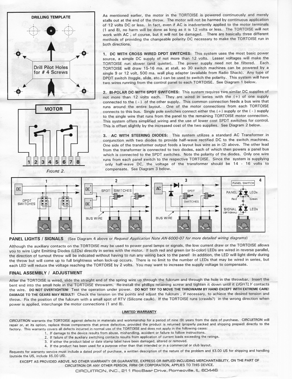
The Tortoise is very easy to use: it takes 12V DC in terminal 1 and 8. Switching the polarity will make the machine to move in the other direction. The Tortoise can be powered either continuously or momentarily. The Tortoise will not be damaged by an AC courant as long as it is less than 12V.
Three electrical wires need to go under the table from the Peco switch to the Tortoise - this is for the polarity of the frog. An addition larger hole is needed to move the throwbar.
First, I use the wired Peco switch to mark the location of the holes from the top of the roadbed.
I then followed the instructions about the size of the hole for the throwbar, but it turned out that it needed to be enlarged horizontally to allow for the spring wire to move freely:
From the top of the table
Under the table
The notice provides a template to locate where to put the screws that hold the Tortoise in place. It is important to draw the line between the frog and the throwbar to make sure the spring wire moves perpendicularly to the stock rails. I use 3/4'' screws with a #4 flat head:
The spring wire then needs to be shaped with pliers according to the instructions. The setup is then straight forward:
Now, I can plug the connector and test!
And from the top; nice and smooth!
Tortoise switching the frog's polarity
Now, I just have to connect the wires from the Peco switch to the Tortoise; the instructions are very clear: the stock rails go in terminal 2 and 3, then the frog in terminal 4. When the Tortoise moves from one position to another, the frog will be connected to the other stock rail, hence switching its polarity.
Today, I look into powering the frog from a Peco switch.
Default Peco electrofrog
By default, the Peco frog gets its polarity when the switch point touches the stock rail. The whole component made of switch points, closure rails, and the frog switch polarity as one of the switch point touches the stock rails. This setup is prone to shorts and to weak power in the frog.
Frog piloted by the switch motor
Peco provides some indications on how to improve the reliability of the frog:
There are three easy steps:
Remove contacts between the frog and the closure rails (and increase the gap)
Add electrical connection on each side between the stock rail and the closure rail
Remove the spring in the throwbar
In this first step, I cut both of the small wires and pulled on them with a plier.
Then, I increased the gap between the frog and the closure rails with a flat screwdriver. This is critical to avoid any electrical shorts:
For the second step, I followed what a YouTube video recommended by continuing the electrical connection from the stock rail, to the closure rail, to the rotating point between the closure rail and the switch point. I did not recommend doing that. It worked fine for the first side, but I struggled a bit on the other side with the soldering iron and heated the rail too much. The plastic melted and the switch is not damaged.
The next 2 photos illustrate the mistake mentioned above:
In the image below, we can see that the plastic melted at a place that is supposed to rotate freely to ensure an easy swing of the switch points.
The third step is to remove the tiny spring in the throwbar:
Lastly, I shortened the crossties near the switch points:
Help from YouTube
I found those two YouTube videos most helpful:
And:
Note that this last video adds a step that can damage the switch and does not seem really necessary.