-->
Showing posts with label lenz. Show all posts

Saturday, October 2, 2021

Switch control


So now that trains are running on clean tracks, let's control the switches and move the trains across the various routes! Except ...


Controlling double slip switches with the ESU ECoS

The ECoS has a 4-way double slip switch in its library. 


It is controlled by two switch motors. The ECoS automatically assigns the next digital address to the second switch motor. I knew that and covered this in this post here.


Unfortunately it didn't work as expected. I could not figure out what was wrong and how to correctly configure and control them. I didn't find anything really helpful online, but with some information gathered online (here and here) and a lot of trial and errors, I got them to work correctly.

Here are the things to pay attention to:

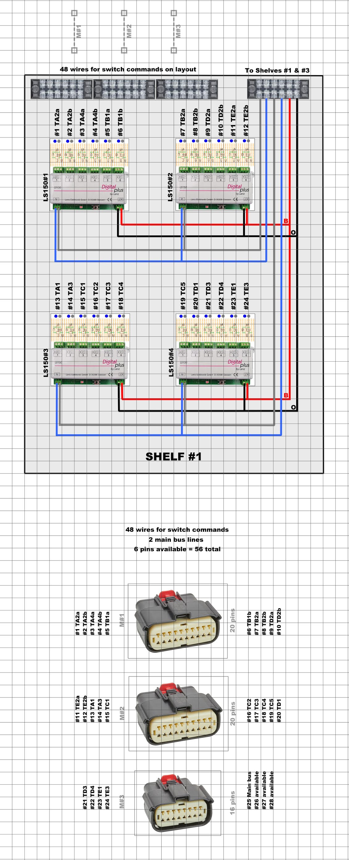
  • Two switch motors with consecutive digital addresses (see above)
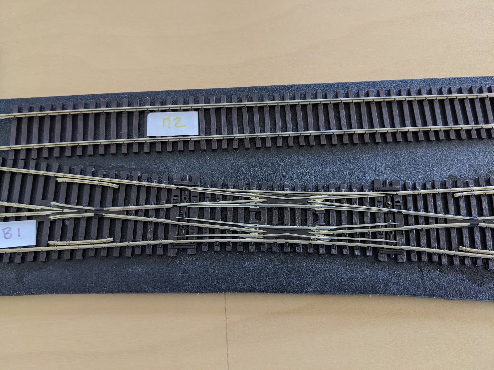
  • The motor with the lower/first digital address has to be on the left side
  • Swap the power wires on one switch engine; this is the trial-and-error part, and it works eventually!


Success!


Two videos of trains crossing the double slip switches:


Friday, July 17, 2020

Shelf #1 digital

In this post, I summarize the digital configuration for all switch motors:


Switch reference Lenz decoder Digital address Switch reference Lenz decoder Digital address
A1 LS150#3 13 C3 LS150#3 17
A2a LS150#1 1 C4 LS150#3 18
A2b LS150#1 2 C5 LS150#4 19
A3 LS150#3 14 D1 LS150#4 20
A4a LS150#1 3 D2a LS150#2 9
A4b LS150#1 4 D2b LS150#2 10
B1a LS150#1 5 D3 LS150#4 21
B1b LS150#1 6 D4 LS150#4 22
B2a LS150#2 7 E1 LS150#4 23
B2b LS150#2 8 E2a LS150#2 11
C1 LS150#3 15 E2b LS150#2 12
C2 LS150#3 16 E3 LS150#4 24

Shelf #1 wiring - part 6

Following the wiring diagram, I wired the 4 Lenz LS150 with the terminal blocks. I initially thought that the fourth terminal block would need to be located on a side, but then I realized I could probably stack them.


Schematic


Here's what I designed on Anyrail:


Placement


I used the following supplies:

Here are these several steps with pictures:


Wiring


I used the following supplies:

Here are these several steps with pictures:


Testing


Now, all Lenz LS150 need to be configured:


Completion


And here's the final result:


Sunday, June 21, 2020

More wiring - part 4

Over the last couple of weeks, I have worked on the other 3 modules for switch controls - as described on this previous post: https://lagaredascq.blogspot.com/2020/05/wiring-part-2.html


And everything together:


I've also tested connecting of ESU modules together to the ECoS Command Station:


Saturday, May 16, 2020

Wiring - part 3

Terminal blocks


After the last two parts of the wiring, I was not very satisfied with my terminal blocks and decided to try out another type of terminal blocks. Here are the links:


The main advantages of this terminal compared to the one I've been using so far is the ability to connect wires from very different gauges and the simplicity of connecting in parallel.

We can compare those two versions:


Tortoise switch motors


Once I wired the 3 sections on each side of the switches, I took on the installation of the Tortoise switch motor. I glued some leftover trackbed between the plywood and the motor to prevent vibrations.


I then mounted the motor with the provided spring (I advise against using anything else: I have one switch with some other wire and I think it is not flexible enough and might damage the switch over time).


I then started the easy wiring of the motors, that's to say without any power to the frog (green wire).


Time for a quick test:


Peco switches


At this stage, I decided to glue these two switches in place on the trackbed with the Woodland Scenics glue:


Temporary wiring


I was ready to see some machines running and omitted to wire the section detection; so based on the diagram I connected all the red wires together:


What we were waiting for!


And finally:


Sunday, May 10, 2020

Wiring - part 2

I continued with the diodes board for the switch decoder. I haven't found yet the appropriate connectors to solder on the PCB, so I'm soldering small wires; all of those components are very cheap, so I can always improve this component later on.

PCB & Diodes 


From there, I just have to connect the PCB to the switch decoder following the documentation:


And it looks like this:


Configuring the switch decoder 


There are two things to configure on the Lenz LS150:
  1. Digital address of each switch command
  2. Pulse duration of the output
The documentation is quite clear and easy to follow.


The idea is that, once the switch decoder is in "programmation" mode, I need to use the address field on the configuration in the ECoS to send values on the LS150. For the tortoise switch motor, a pulse duration of 3.5sec seems appropriate - 3sec might be okay too.


All together ... 


And here's the result:


Sunday, December 15, 2019

Partially putting everything together

This is an attempt to put all the components together. I chose the front section with the two double slips. Here's how it looks on Anyrail:


It's getting interesting ...

I added a stripboard for the two 1N4001 diodes required for each output of the Lenz LS150. I think each stripboard will carry six sets of two diodes, so each stripboard will be dedicated to one single LS150. Here are two designs; I have not decided yet which one I will go with.


The stripboards are fairly cheap and not easy to cut, so it might make sense to keep the board as one piece and use the space for labeling and securing to the control panel.

For reference, here's the board I bought at MicroCenter: https://www.microcenter.com/product/505440/velleman-eurocard-full-line-fr4


Mine is reference ECL1/2, but it basically the same.

Sunday, December 8, 2019

Switch - Part 3 - DCC command of switch motor

I finally got around the DCC control of a switch motor. I use the following components:

  • ESU ECoS Command Station - link
  • Lenz LS150 - link
  • Atlas Master Generator - link
  • 2 diodes 1N4001
I chose the solution with the LS150 module because it needs a separate power supply to control the switch motors. Considering the number of switches I have, it might have been too much power taken from the main tracks to power the switches. The only downside I can see is that the Tortoise will relax at the end of throw as it is designed to be used as a stall device and the LS150 cannot keep the power on all the time. 

I followed the LS150 instruction manual and the wiring diagram is fairly easy:


And here's what it looks like in real life:


A couple of details regarding the configuration of the LS150:

  • You cannot control the pulse duration from the ECoS; it needs to be configured with the LS150 itself - see below
  • In the video, I set the pulse duration to 5 sec; I believe it is a bit too long but it cannot harm the switch motor since it expects to be powered all the time
  • The english version of the instruction manual can be found here.