-->
Showing posts with label cad. Show all posts

Sunday, July 17, 2022

Streets and buildings outline - part 5


Same process ...


And here's what we have so far:


And in one video:


Sunday, July 10, 2022

Streets and buildings outline - part 4


Today, I didn't have time to continue on building draft structures, so I focused on pictures of the facades. 

See below:


11 rdM #111 - 11 rue des Martyrs - Parcelle 111

13 rdM #110 - 13 rue des Martyrs - Parcelle 110

15 rdM #109a - 15 rue des Martyrs - Parcelle 109

15 rdM #109b - 15 rue des Martyrs - Parcelle 109

For this last one, I had to combine two pictures together since the house is quite tall. I fixed the perspective and dimensions on each of them before combining them and the fit is very good.


Saturday, July 9, 2022

Streets and buildings outline - part 3


Now that I have the outline at the exact scale, I can easily create draft building out of foam boards. There's nothing special about this task; just cutting and gluing foam boards at the right dimensions. I wrote the house number in the back and glued a picture of the facade in the front (as explained at the end of this post).


This section covers those 5 houses:

  • 1 rdM #116 - 1 rue des Martyrs - Parcelle 116
  • 3 rdM #115 - 3 rue des Martyrs - Parcelle 115
  • 5 rdM #114 - 5 rue des Martyrs - Parcelle 114
  • 7 rdM #113 - 7 rue des Martyrs - Parcelle 113
  • 9 rdM #112 - 9 rue des Martyrs - Parcelle 112


Tuesday, July 5, 2022

Streets and buildings outline - part 2


After my previous post, I was still thinking about how to print the DXF file at the exact scale, so I can see how it would look on the layout. I unsuccessfully tried various software and ultimately started to look deeper into AutoCAD. Thankfully, there's a 30-day free trial of AutoCAD LT that seems to be a lighter and cheaper version of AutoCAD.

Those two videos were the most helpful:


After multiple attempts, here are the steps I took in AutoCAD.

Rescaling


As mentioned in my previous post, CAD software do not have units, but rather "drawing" units. The "real" units will come into play when exporting into PDF. Therefore, I decided that one drawing unit will be 1mm at HO scale. Going back to my reference point from my previous post, 25rdM #100 should have a width of 103mm (25 rue des Martyrs that is lot #100 on the cadastral plan).

Here are the steps in AutoCAD:
  • When opening the DXF file, most CAD software will not display much at all. The first step is to click on "Zoom Extents". This will zoom out or in to fit all of the objects in the drawing to the edges of the screen so you can see the entire drawing.
  • Select all components on the drawing
  • Scale using the reference point
  • Measure again to make sure


Layout and printing


In AutoCAD, there are usually two tabs at the bottom: a model and a layout. The model is the actual drawing and the layout is used for formatting before printing. Therefore, you can have multiple layout tabs (I don't know about models).

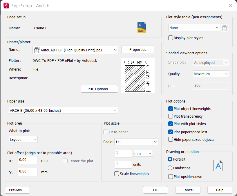
When starting a new layout, AutoCAD asks for a page setup. This is what I have in my case:


The main items to note:
  • Printer is an export to PDF
  • Paper size is Arch E, which is the largest Staples can print
  • ==>   Scale is 1:1 and 1mm is 1 unit   <==
This last point is the key here to make sure it will be printed at the exact scale.


We then have a blank page. We need to click on Rectangular in the Layout menu and draw a rectangle as large as possible on the page:


The drawing is automatically added inside the rectangle:


You can double click anywhere inside the drawing to zoom (mouse wheel) and pan (just type PAN):


This is great progress, but obviously we lost the scale here. So, it is important to re-adjust the scaling in the layout mode:


The layout is now ready to be exported into a PDF file. In my case, I have an extra step since the area will cover multiple sheets of paper, so I need to export one PDF, then move the drawing, then export again, and so on ... I ended up with 4 PDFs:


I only have a 30-day trial, so a next step will be to investigate nanoCAD as it looks very similar to AutoCAD and is basically free.


Thursday, June 23, 2022

Streets and buildings outline - part 1


Now that the tracks are glued and wired, it's probably time to start thinking about the scenery. The first stage is ballasting and track weathering, but I need to do a bit of research on this to decide how to proceed. The second stage is to start drawing the outline of the streets and building and to decide the exact location.

The main issue here to have an outline at the exact scale. Here's my current thinking:

  • I got a DXF file from cadastre.gouv.fr
  • On that same website, I measure the length of the front of buildings
  • I then convert to those dimensions into HO scale
  • I build a rough prototype in foam board


DXF file


I found multiple software that can open a DXF file; those include AutoCAD, nanoCAD, or QGIS. The issue is that the DXF file has drawing units, not real measures. Therefore, measuring in the DXF file does not help scaling the outline. 


Cadastre


I chose one building: 25 rue des Martyrs that is lot #100 on the cadastral plan:


It is about 8.99 meters in real, so approximatively 10.3 cm in HO scale.


Autodesk Viewer


As I was doing some research on CAD software, I came across this free tool from Autodesk: Autodesk Viewer. It allows to open DXF file and do basic operations. One of them is to make measures and smartly enough, there is a calibrate function:


House facade


Now that I have the width of the houses, I need the other dimensions. For this task, I will use my own photos, as what you can get from Google Street View is too distorted:

Google Street View

My photo


While the photo is quite good, I still need to fix the perspectives. I was pleased to find this article that explains how to easily do this in Gimp:
  1. Load the picture in Gimp
  2. Place 2 vertical and 2 horizontal lines to help framing the perspective:
    • Drag from the left or top ruler to get a line
    • Place the lines where things should be vertical or horizontal, like doors, windows, and roof cornice
  3. Use the Perspective tool (Shift+P)
    • Drag the corners until things start to align to the reference lines
    • Iterate until it aligns nicely
  4. Select the facade and crop to it
  5. Use Scale Image or Print Size to scale the image
  6. Print from Gimp to get a scaled print of the facade

Here are all those steps in images:


Other online maps


Besides the cadastral website, I think those two can also be helpful: