-->

Friday, February 22, 2019

Digitization of a BB 67000 - Part 2 - Lighting kit

This is the second part of the digitization focusing on getting better lighting for the engine (see here for part 1).

Wiring the lighting module


There are 3 wires to solder: blue (BL), red (RO), and white (BC). The instructions are rather clear on the wiring.


It does not say on the instructions, but the wires must be soldered as shown above. The connectors are pointing up, so the wires would otherwise have to be folded. 


Now, I put the decoder in place and we are ready for some testing.


Testing the lighting module


The white lights for one direction:


And the red lights for the other direction:


In a video:


Now, testing both sides:


And the video:


Installing the lighting module


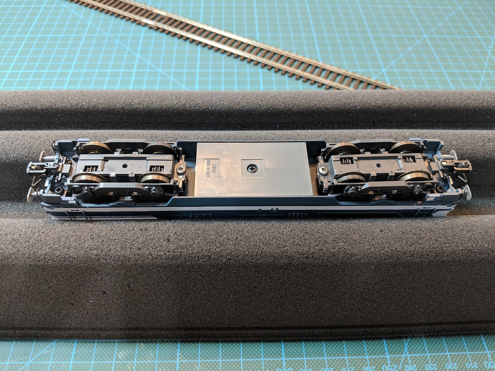
This is when I realized this body needs a 3-light module and not a 2-light module. I switched to another body from BB 67382 (Lima reference 208576).


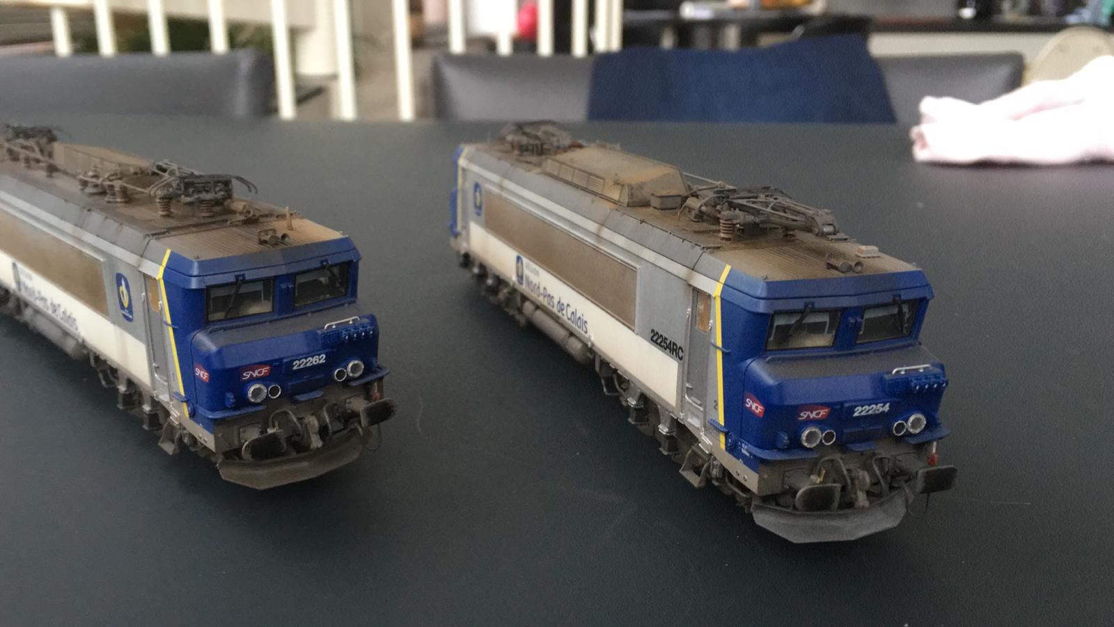
Below, on the left side, this is a 3-light engine. On the right side, this is a 2-light engine.


One thing not mentioned in the instructions is that as you remove the light guide, it will leave an empty space inside the body and will not look nice when looking towards the front of the engine. I, therefore, decided to cut the 4 small pieces of light guide on each side and glue them in place. They should be flush with the body.


I then used Super Glue to glue the light circuit board with the 3D-printed brace:


The next step is actually a bit tricky; I followed the suggestion from the instructions to use double-face tape to position the lighting module on the body of the engine. I've tried some clear and very thin tape, but it would not be sufficient contact between the module and the body. I opted for a much thicker tape that is used for frames. Look below for the white tape:


A quick test to make sure everything works:


Now, when I tried to put the body and the chassis back together, I had to force quite a bit. This is because of the thickness of the white tape and ultimately I had to use a flat screwdriver as a lever:


And that is it!

The outcome


Here's the final result:


BB 22200 Nord-Pas de Calais

Just some nice pictures. These are the LS Models 10437 weathered and with new numbers: BB 22254 and BB 22262.


Monday, February 18, 2019

Digitization of a BB 67000 - Part 1 - Decoder

I own quite a few BB 67000 from Lima, Rivarossi, and Jouef that are analog and prior to the digital era, which means that they are not ready to receive a decoder.

Loco Revue № 851 from June 2018 tells us how to make such a transformation and how to replace existing lights with CMS LEDs. I provide a link here. I bought 3 items from Miniatures Passion:

  1. Circuit board MPPE451 - item and instructions
  2. Lighting kit "2 lights" MPEL110CMS - item and instructions
  3. Decoder ESU 54617 Lokpilot V4.0 Plux22 specifically programmed by Miniatures Passion - item


Note that Miniatures Passion sells similar kits for other engines; the full list is here.

I started by transforming BB 67329 from Lima (reference 208011). It turned out that this model is a 3-light engine, not a 2-light one. I, later on, switched the body with BB 67382 (reference 208576).

Opening the engine 


To open the engine, I had to remove the screws in the middle of the chassis and two on each end-side underneath the buffers.


Then, I had to spread the sides of the body to separate it from the chassis. It goes fairly easily. The footboards fell aside by themselves.


 I kept all the small parts separately.


I did a quick test on analog, specifically to see how the lights work.


I took several pictures of the wiring, just in case I messed up something - this is for reference below:


Preparing the circuit board


Since I planned to plug the lighting module, I soldered the resistors for that module in the first place. Then I tinned the various connectors as per the instructions.


Installing the circuit board


I unsoldered the wires from the existing circuit board. I did intend to keep the current wires.


To remove the board, I unclipped it from the board. There are 4 black clips in the middle of the board.


To remove the lighting module on each side, I just had to put a small screwdriver between the small circuit board and the chassis and do a gentle twist. It came off pretty easily.


Then, I clipped the new circuit board into the same position and soldered the wires as per the instructions:


One end with a wire for each trackside:


Wires to the motor:


The other end with a wire for each trackside:


And that is it!


Testing the newly digitalized engine


First, on the test stand:


Then, on the tracks: