-->

Friday, October 9, 2020

Custom test bench - part 3: Wiring


Wiring


The wiring was fairly straight forward:


Finished product


And here's the finished test bench:


I left quite some space on the panel to allow for a future installation of a LED display to show voltage and current consumptions. I'm thinking about an Arduino project.

Sunday, September 27, 2020

Custom test bench - part 2: Components & Diagram

 Since the goal for this test bench is to host all testing options, I have the following inputs:

  1. DC power
  2. DCC with my Roco Z21 multiMAUS
  3. ESU LokProgrammer
  4. AUX which is in fact my ESU ECoS 2 Command Station
and I have 3 outputs:
  1. Track 1
  2. Track 2
  3. ESU Decoder Tester
Each track can take any of the 4 inputs, but obviously, the Decoder Tester will only take the 3 DCC inputs.


Components


Here's the list of all components for this part of the test bench:
  • Athearn 9997 Trainpak Power Pack - link
  • Roco 10810 Z21 multiMAUS - link
  • ESU ECoS 2 Command Station - link
  • ESU 53451 LokProgrammer - link
  • ESU 53900 Decoder Tester - link
  • 2 Rotary Switch 2 Pole 5 Position - link
  • 1 Rotary Switch 2 Pole 4 Position - link
  • 3 knobs - link & link
  • USB A panel mount connector - link


    Diagram


    A simple wiring diagram:


    Sunday, August 16, 2020

    Custom test bench - part 1: Woodworking

    As I need to digitize a significant number of engines, it became clear that I need a test bench that can host the DC and DCC stations. I also purchased a decoder tester and a decoder programmer from ESU; those will also be placed on the test bench.

    The first step is the woodworking part. I didn't do any precise plans, just going off by the size of the plywood I got and hoping wood glue will do magic.
    • 6mm 1/4 x 12 x 24 Inch Premium Baltic Birch Plywood - here


    I didn't take pictures of every step, unfortunately.

    Saturday, August 1, 2020

    Digitization of a Z 24500 Jouef - intro

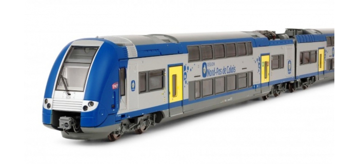
    This is going to be a multi-part post on the digitization of a Z 24500 from Jouef and more specifically the Nord-Pas de Calais version HJ 2001:


    Parts

    In this section, I'm listing all the components for this work:

    • ESU 54614 LokPilot v4.0 for the side without a motor to control headlights and interior lighting; purchased from Train Modelisme
    • ESU 54671 PowerPack Mini for LokPilot V4.0 to prevent flickering of the interior lighting; from eBay
    • ESU 58419 LokSound v5.0 for the DCC Sound control; purchased from Train Modelisme
    • LED strip, warm white 4000K, 600 SMD on 5 meters, 12V:
      • 3 colors: yellow 3000K, warm white 4000K, daylight 6000K - the warm white is obtained by turning on both the yellow and the daylight LEDs; purchased from Amazon
      •  1 color; purchased from Amazon
    • Miniatronics 3-Pin Micro Mini Connectors MNT5000301; from eBay
    • Passenger models purchased from Amazon


    Resources


    Several links to articles and posts about digitization and interior lighting:
    And links for the real unit:
    And some videos to see the interior colors:
    • Video from Simply Railway
    • Video from SteveTC59
    • Video from Productionstudio 92


    The next post will be about the installation of ESU 54614 in the side without a motor.

    Saturday, July 25, 2020

    Shelf #2 wiring - part 7

     This shelf carries the ESU ECoSDetector modules. I have the following items:
    The ESU 50094 has 16 inputs for detection, but only 4 are RailCom. The ESU 50098 has 4 RailCom inputs.


    Schematic


    Here's what I designed on Anyrail:


    Wiring


    Here are these several steps with pictures:


    Completion


    And here's the final result:


    Friday, July 17, 2020

    Shelf #1 digital

    In this post, I summarize the digital configuration for all switch motors:


    Switch reference Lenz decoder Digital address Switch reference Lenz decoder Digital address
    A1 LS150#3 13 C3 LS150#3 17
    A2a LS150#1 1 C4 LS150#3 18
    A2b LS150#1 2 C5 LS150#4 19
    A3 LS150#3 14 D1 LS150#4 20
    A4a LS150#1 3 D2a LS150#2 9
    A4b LS150#1 4 D2b LS150#2 10
    B1a LS150#1 5 D3 LS150#4 21
    B1b LS150#1 6 D4 LS150#4 22
    B2a LS150#2 7 E1 LS150#4 23
    B2b LS150#2 8 E2a LS150#2 11
    C1 LS150#3 15 E2b LS150#2 12
    C2 LS150#3 16 E3 LS150#4 24

    Shelf #1 wiring - part 6

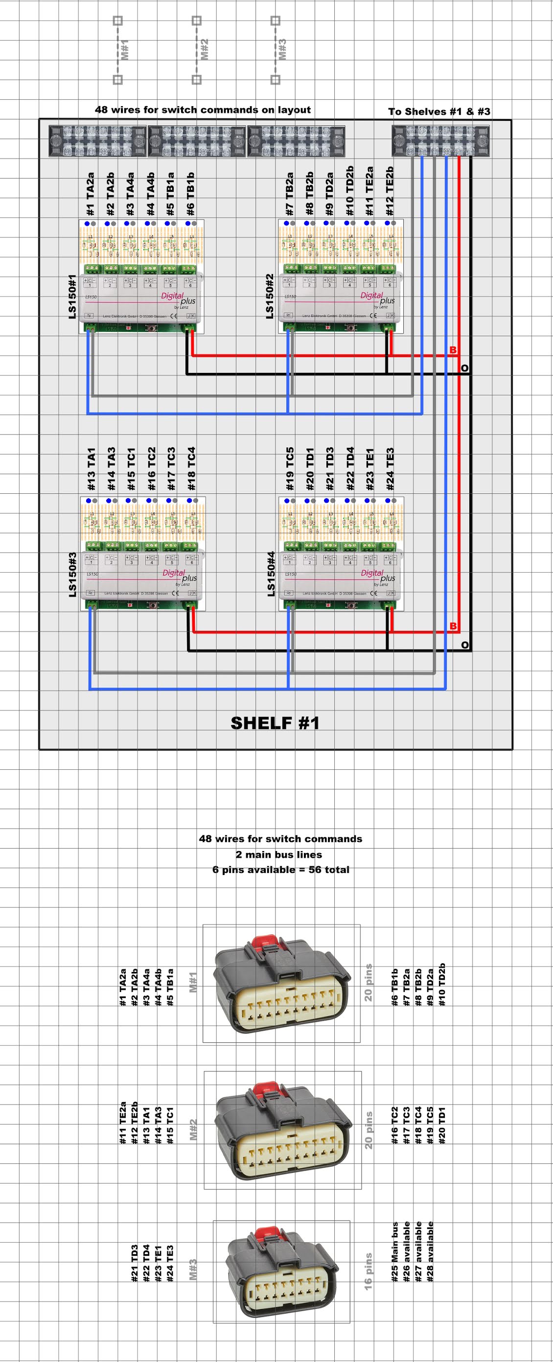
    Following the wiring diagram, I wired the 4 Lenz LS150 with the terminal blocks. I initially thought that the fourth terminal block would need to be located on a side, but then I realized I could probably stack them.


    Schematic


    Here's what I designed on Anyrail:


    Placement


    I used the following supplies:

    Here are these several steps with pictures:


    Wiring


    I used the following supplies:

    Here are these several steps with pictures:


    Testing


    Now, all Lenz LS150 need to be configured:


    Completion


    And here's the final result:


    Sunday, July 5, 2020

    Alpha Meter

    As mentioned in this previous post, I purchased a 2U panel for an electronic display. This is for the Alpha Meter from DCCconcepts - https://www.dccconcepts.com/product/alpha-meter-for-dc-or-dcc/


    It is a digital meter for use on DC or DCC layouts. There are only two wires in, two wires out. It automatically adjusts for AC, DC or DCC power and even compensates for its own load, leaving only readings relevant to the layout operation. 


    It is that simple!


    Installation


    I used the Dremel to cut through the steel plate. It took a while, but no problem here:


    Result


    Saturday, July 4, 2020

    Wiring diagram - part 5


    I completed the schematics on Anyrail:


    Sunday, June 21, 2020

    More wiring - part 4

    Over the last couple of weeks, I have worked on the other 3 modules for switch controls - as described on this previous post: https://lagaredascq.blogspot.com/2020/05/wiring-part-2.html


    And everything together:


    I've also tested connecting of ESU modules together to the ECoS Command Station:


    Thursday, June 11, 2020

    Rack for all electronic modules

    After a bit of research, I decided to go for a server rack to hold all the electronic modules as well as the ESU ECoS command station. 

    Here's what I purchased:


    This unit works well as it can slide under the layout table and I can put the ESU ECoS command station on top of it when operating the layout.


    One shelf for the Lenz LS150, one shelf for the ESU ECoS Detector, and the top one for the command station.


    The rack came with a PDU, but the outlets were front-facing and it didn't work since the sliding shelves take the complete depth of the rack. This PDU has surge protection and the outlets are in the back.


    I'll show on another post why I wanted this panel. It will hold an additional electronic display.


    Overall, it took a long while to build the rack. It's quite cheap, so it came with some defects; the biggest one of which is that it is slightly wobbly. Here's the final result and I'm pretty happy about it:


    Tuesday, May 26, 2020

    ESU ECoS - Peco double slip switch

    I forgot to mention one rather important detail in my previous post: how to configure the ESU ECoS for a Peco double slip switch. On the ECoS, a double slip switch has only one digital address. The thing to know is that the ECoS will automatically assign the next address to the second motor.

    Therefore, the double slip switch B1 has addresses #1 (TB1a) and #2 (TB1b).

    Monday, May 18, 2020

    ESU ECoS - Engine image

    This is a short post to list the steps to add an engine image on the ESU ECoS:

    1- Login to http://www.esu.eu/en/downloads/loco-pictures/
    2- Download the image on your computer
    3- Login to the ESU ECoS http://192.168.1.197/en/index.html
    4- Upload the image
    5- Restart the ESU ECoS