-->

Monday, December 2, 2019

Train detection and identification

To ensure automation, train detection is required. I'm using ESU ECoS Detector: http://www.esu.eu/en/products/digital-control/ecosdetector/ecosdetector/

I wanted to run a quick prototype to make sure I understand how it works before going on the actual layout.


Train detection


The English manual is easily found on the Internet and the wiring is pretty straight forward: one of the tracks is isolated and gets its feed from the ECoSDetector instead of directly from the ECoS Command Station. The ECoSDetector gets a direct feed from the ECoS Command Station.


It is very important to follow 0 is black and is direct to the track, whereas B is read and goes through the ECoSDetector.

Now, it is easy to link the ECoSDetector to the track diagram on the ECoS Command Station by using the icon circled in red below:


When everything is wired up and correctly configured, here is what happens:


The track in red shows that this section is occupied!


Train identification


This is all great, but we actually don't know which engine is on that occupied section. Enters RailCom. Decoders equipped with the RailCom protocol can communicate back to the digital station.

I need to insert a RailCom box on the track diagram on the ECoS Command Station by using the icon circled in red below:


So, same as above, but now with RailCom:


We actually see the name of the engine on the track diagram. Unfortunately, ECoSDetector 50094 has only 4 RailCom inputs out of the 16 inputs. However, ESU offers the ECoSDetector RC 50098 that provides only RailCom inputs, but one module has only 4 inputs: http://www.esu.eu/en/products/digital-control/ecosdetector/ecosdetector-rc/

Friday, November 29, 2019

ECoS Command Station

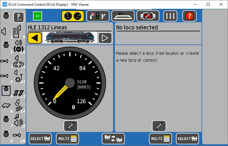
I bought the ESU ECoS Command Station a while back, but I never posted here my first steps with it.

Connection to Wifi


The first thing is to connect the ECoS Command Station to the wifi for two main purposes:

  1. Update firmware
  2. Upload custom images for locomotives
The ECoS Command Station has an ethernet port, so I bought a Wifi bridge here


I don't remember how to configure it, but it was very easy; I probably had to connect it directly to a laptop for the first setup.

You can then check the IP address of the ECoS Command Station on the network:


ECoS Command Station portal


I can now access the portal of the ECoS Command Station from a web browser on the network. This is the URL: http://192.168.1.197/en/index.html


Custom images for locomotives


There are plenty of user-generated images for locomotives beyond those provided by default by ESU. They can be found and downloaded here: http://www.esu.eu/en/downloads/loco-pictures/


Once you save the image on your computer, you can upload it to the ECoS Command Station from its portal.


You will need to restart the ECoS Command Station before you can see it on the station itself.


Wiring ... completed

All tracks are finally soldered and positioned!


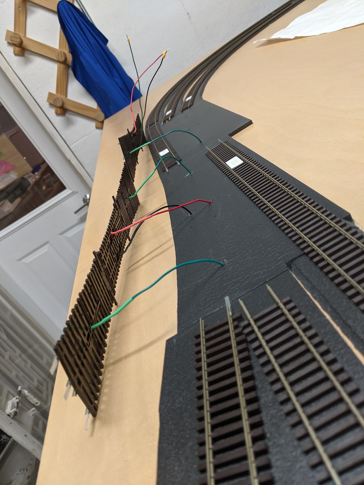
The next step is ... more wiring ... All the "little" wires are underneath the plywood and need to be connected to the main bus feeder:


Saturday, November 9, 2019

Wiring ... continued

All tracks and switches have been soldered!


I've tried a slightly different approach to soldering switch, especially for the frog - green wire. I actually broke a frog wire of a double slip and it is a very expensive mistake. For now on, instead of having to drill right underneath the frog, I leave more of the bare wire from Peco that runs under the sleeper and I drill right next to the sleeper:


Sunday, October 20, 2019

Wiring

Now that the track-bed is done and the tracks positioned on top of the track-bed, it is time for wiring. There are three activities here:

  1. Wiring switches
  2. Wiring tracks
  3. Drilling through the plywood for those wires

Wiring basics


I use solid color cables gauge 22 to wire switches and tracks. I also use heat shrink tubes to protect the solder between the small wire from the switch and the wire cable. 
I bought the wires and the tubes at Micro Center:

Wiring switches


I went through this step in detail in this post here. I'm only putting pictures.

This is for a Peco Double Slip Switch (SL-U8363 Code 83 Unifrog #6). 


This is for a simple Peco Electrofrog Switch.


This is quite time consuming:


Wiring tracks


This is very straight forward. I used either a fiberglass scratch brush (https://smile.amazon.com/gp/product/B002RMCFZM) or a small file to prepare the bottom of the track for soldering.


Then, I use liquid electrical tape to protect the solder - https://smile.amazon.com/gp/product/B0000AXNOD


Drilling through the plywood for those wires


Once all wires have been soldered to switches and tracks, I put them back in place and drill through the plywood. For wires, I use a 5/32 bit for the wires, and a 1/2 bit for the switch motor.


It is time consuming and will probably take a few weeks to complete.

Saturday, September 28, 2019

Track-bed is done!

All track-beds have been positioned and glued down:


The next steps are to solder all the wires to the tracks and switches, make holes in the platform for all the wires and the moving points of the switches, then glue the tracks!

Friday, September 20, 2019

Track-bed

Since I made the outline of all the tracks, I removed them and I can start installing the track-bed foam.

Outline


Track-bed

I am using the Woodland Scenics products:

I'm pretty sure any white glue would do, but I decided to go for peace of mind. The process is fairly easy: put some glue on the plywood, lay the foam, and put some weight for 10 minutes to ensure full contact:


The straight sections are very easy and fast to install:


The curves are a bit tricker. Here's my process. I cut the foam in half along the long side - there is a pre-cut that I follow with a hobby knife. I made some blue marks on a piece of plywood to serve as a gauge: the center mark is the center on the track, the two other blue marks on the side are for the tracks, and the sides of the piece of wood are the bottom of the track-bed.
I then trace the center of the tracks with the blue Sharpie and put pins. These pins will hold the position of the curved track-bed:


The curved sections are actually quite time consuming. Should be done soon ...